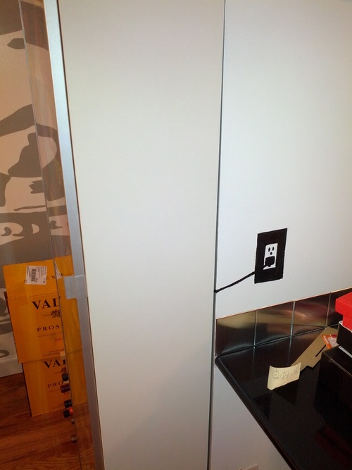
This is my first “real” (non-blink an LED) arduino project. The problem: our bar blocks the lightswitch for the light over the living room table. The solution: control the light by touching a picture around the corner. Touch the picture once to turn the light on and touch it again to turn the light off.
Supplies:
1 Arduino (I used Adafruit’s Adruino Micro without headers): $22.95
Bare Conductive electric paint: $24.95
1 330k resistor
1 usb power supply: $5.95
1 usb cable (A to micro B): $3.95
1 arduino-controllable relay (I used the Sparkfun Beefcake Relay Control Kit): $7.95
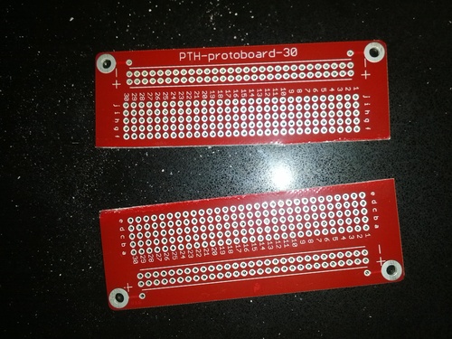
1 solderable breadboard: $4.95
1 washer (optional)
1 magnet (optional)
This thing ended up working in a fairly strightforward manner. The picture itself is a capacitor and touching it changes its electrical resistance. The arduino is monitoring the picture and when the resistance changes in a way that it is looking for, the arduino triggers the relay. That relay is attached to the light so on is on and off is off. The hardest part is setting the trigger threshold.
Here is a crappy and probably incorrect sketch of the circuit:
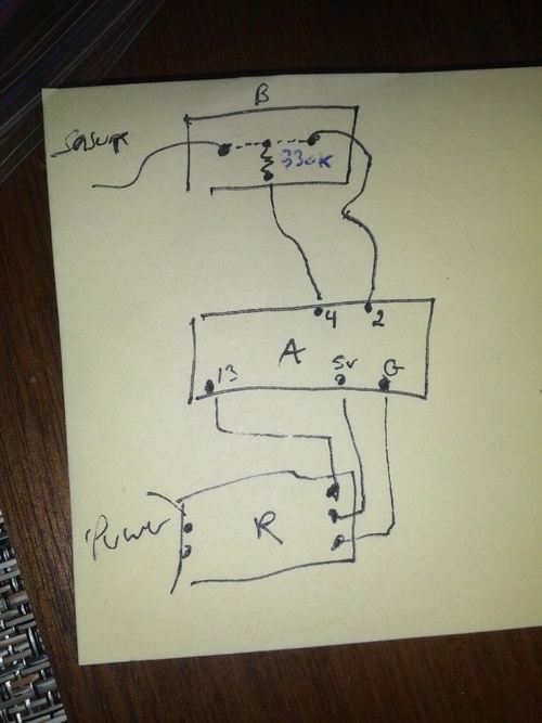
B is the breadboard, A is the arduino, and R is the relay. That word in the upper left is “sensor” because that wire goes towards the picture. The dotted line on the breadboard shows that those two points are connected, and the zig zag line is the resistor.
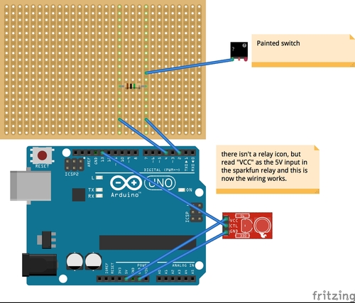
(Edit 1/15: here’s a better picture using fritzing)
The first step is probably to paint your picture with the paint. As far as I know the picture can pretty much be whatever you want. The only thing to be aware of is how you are going to connect it to the arduino. The bare conductive tutorial that existed when I started this project (but that is now gone) suggested using the paint to “glue” a magnet to the wall. I did that
There is no reason that the connection point is far away from the main picture. The wire is purely aesthetic - it keeps everything behind the bar and around the corner. Once you have the magnet on the wall you can connect it to the arduino by soldering a washer to the end of a wire.
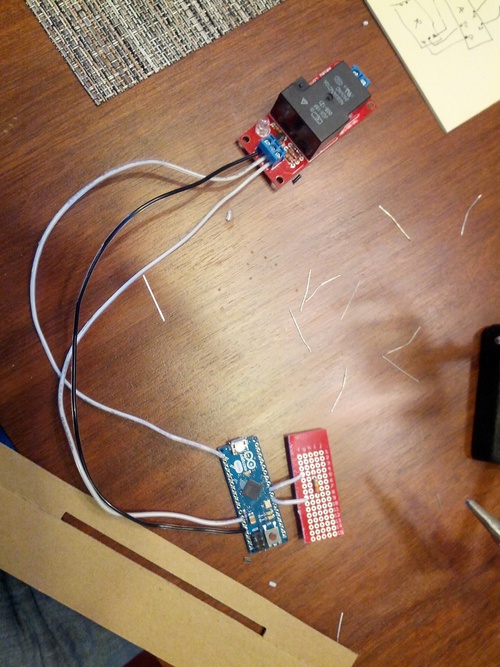
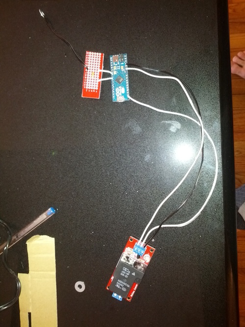
The next step is to build the circuit. The circuit is made up of three elements: the arduino, the relay, and the breadboard.
The breadboard is not very complicated. In fact, I probably could have just soldered all of the parts together to let them dangle in space. But breadboards are cheap and I wanted this to look somewhat clean, so I decided to go for it. Since this is a small circuit, I just cut the breadboard into smaller pieces.
I then connected the wires and the resistor. Remember that everything in the same number row is connected electrically.
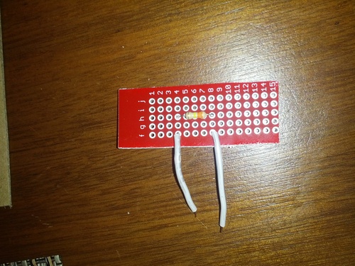
I used a 330K resistor. The advantage of a 330K resistor (compared to, say, a 10K resistor) is that it increases the spread between the value returned by the picture when no one is touching it and when someone is touching it. (Edit 1/15: after having some problems with this - mostly the lights flashing on and of and/or the switch not responding to a touch - I went back and reread the capacitive sensor arduino library documentation. I was using a resistor that was way to small. The documentation recommends at least 1 megaohm for touch and larger ones for proximity. Hopefully changing this will address some of my problems). This spread becomes important when you are setting the threshold. We’ll get to that in due time.
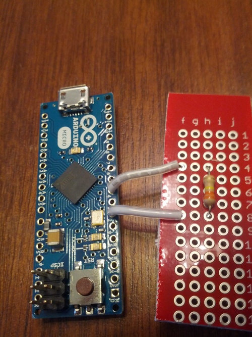
Once the breadboard is done it is time to connect it to the arduino. I got a headerless arduino because I wanted to be able to solder the connections and I got the micro arduino because I wanted the final assembly to be as small as possible. Connect the wires to the proper pins (2 and 4 if you are using my sketch).
Next you need to connect the arduino to a relay. But what is a relay and why do you need it? In a perfect/easy world, you could just use the ardino to power the light. Activating a pin would send enough electricity towards the light to turn it on. In our imperfect/hard world, arduinos work at fairly low voltage while overhead lighting works at a fairly high voltage (the upside of this is that it is hard to kill yourself with the power coming out of the arduino). A relay is essentially a high-voltage-controlling switch that is controlled by a low-voltage trigger. When the relay gets the signal from the arduino it activates the high power switch controlling the lights. While these two switches are connected insomuch as the low voltage can control the high voltage, they are separate so the high voltage does not destroy the arduino.
You need to connect three wires from the arduino to the relay: 5v, ground, and control The 5V and ground map directly from the arduino pins to the relay port. The control pin is pin 13, which also controls the onboard LED. The default state for the relay is off so when the on board LED is off (and pin 13 is off) the relay will be open and when the on board LED is on (and pin 13 is live) the relay will be closed.
The next wire to connect is the one that goes from the breadboard to the picture (in the upper left). Solder it inline with the wire connected to the 2 pin.
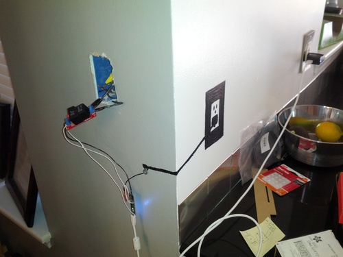
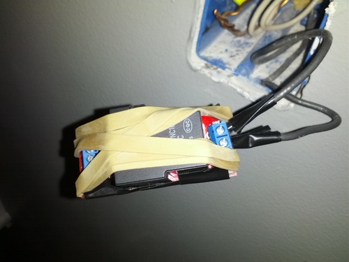
You can now install the circuit. I decided to replace the lightswitch with the relay. The good thing about this was that it put the relay close to the power controlling the light. The bad thing was that it exposed the relay connections to the ground that remained in the lightswitch port in the wall. In order to prevent accidental shorts I wrapped the relay in rubber bands and electrical tape. You can also see that the main wire is screwed into the relay (don’t forget to turn off power going to the light while you do this!).
Now connect the arduino to power with the USB cable and power supply.

With that done it is time to program the arduino. Make sure you have the capsense library installed.
Here is the sketch I used:
//make sure to install the CapSense Library then upload to your Arduino.
//for more information on the basic workings of this sketch check out http://bareconductive.com/capacitance-sensor
#include <CapacitiveSensor.h>
#define MAINSpin 13
const int threshold = 2000; //This is the threshold that you should adjust after watching the serial port. The MAINSpin is only set high if “total 1” is greater than this number
// currently set for a 330K resistor plugged into the wall outlet
// find the lowest possible number that won’t get triggered by random environmental factors
// if the light is on all the time the value is too low
// if the light tends to flash on and off it is close, but still too low
int val = 0;
int old_val = 0;
int state = 0;
int Touch = 0;
CapacitiveSensor cs_4_2 = CapacitiveSensor(4,2); // Your resistor goes between pins 4 & 2. Your pad of paint should be connected to pin 2
void setup()
{
pinMode(MAINSpin, OUTPUT);
digitalWrite(MAINSpin, LOW);
cs_4_2.set_CS_AutocaL_Millis(0xFFFFFFFF);
Serial.begin(9600);
}
void loop()
{
val = Touch;
long total1 = cs_4_2.capacitiveSensor(100);
Serial.println(total1);
Serial.println(“ ”);
if (total1 > threshold){
Touch = 1;
} else {
Touch = 0;
}
if ((val == HIGH)&& (old_val==LOW)){
state = 1-state;
delay (50); //delay for debouncing
}
old_val = val;
if (state == 1) {
digitalWrite(MAINSpin, HIGH); //turn LED ON
} else {
digitalWrite(MAINSpin, LOW);
}
}